Pressure switch MDR 3
Downloads
Technical specifications
- Voltage type
- Three-phase current (A.C.)
- Type
- Electro-mechanical
- Voltage
- ≤ 400 V
- Contact function
- 3 NC contacts
- Gold-plated contacts
- no
- Pressure adjustment
- Pressure difference adjustment (standard)
- Pressure range (bar)
- ≤ 35 Bar
- Pressure coupling
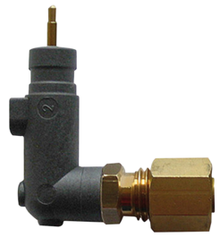
G1/2" female thread (main pressure coupling G1/2", pressure connector material = die-cast aluminium)
G1/4" aluminium female thread (main pressure coupling G1/4" die-cast aluminium)
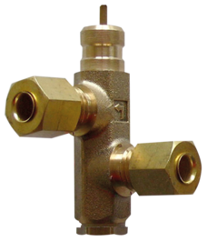
F4 1/2" aluminium female thread (main pressure coupling G1/2", 3 side outlets G1/4", pressure connector material = die-cast aluminium)
F4 1/4" aluminium female thread (main pressure coupling G1/4", 3 side outlets G1/4", pressure connector material = die-cast aluminium)
F4 3/8" aluminium female thread (main pressure coupling G3/8", 3 side outlets G1/4", pressure connector material = die-cast aluminium)
F4 1/4" NPT (main pressure coupling 1/4", 3 side outlets 1/4" NPT (National Pipe Thread) female thread, pressure connector material = die-cast aluminium)
- Overload relay
- possible (accessory)
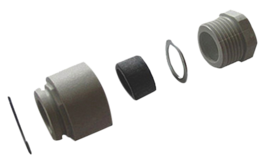
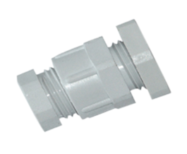
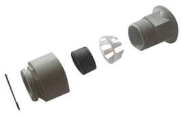
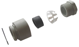
- Cable entry gland
mit 2 x WN (Würgenippel) (Zubehör PG11-16)
- Relief valve
- without (accessory EV, AEV)
- Mechanical On/Off (EA)
- with/without On/Off
- Rated frequency
- 50 Hz / 60 Hz
- Rated operating current (Ie)
-
- max. media temperature
80°C
- Motor switching capacity
- 7,5 kW (11kW - auf Anfrage)
- Protection class
- IP 54
Applications
Certicates & Permits
At a glance
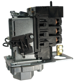
- High-performance pressure switch for 3-phase voltage
- for compressors / for pumps
- for North American market
- Pressure connector material = die-cast aluminium
- optionally with auxiliary switch, pressure scale
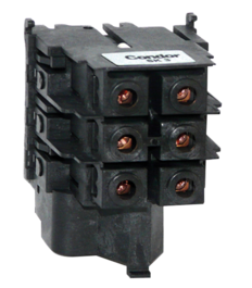
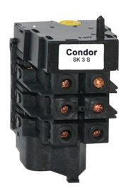
- Overload relay (optional)
- Oper. hours counter (optional)
- Motor switching capacity 7.5 (11) kW / 20 HP
- max. cut-out pressure 35 bar • 3-pole (NC)
Its robust and hard-wearing design ensures a long service life, also under high loads. The MDR-3 pressure switch is fitted as standard with the possibility for pressure difference adjustment. Two adjusting screws permit switching point and hysteresis to be adjusted, whereby the cut-out point is first adjusted via the main pressure spring, and then the cut-in point via the pressure difference setting. By selecting a pair of values for cut-in and cut-out pressures, an intersection point is determined in the diagram. If the point lies within the shaded area, this pair of values can be adjusted on the pressure switch. If the point lies outside the shaded area, this pair of values cannot be adjusted on the pressure switch. Two adjusting screws permit switching point and hysteresis to be adjusted, whereby the cut-in point is first adjusted via the main pressure spring and then the cut-out point via the pressure difference setting.

